CAD에서 CNC까지: 디지털 설계를 기계 가공 부품으로 변환하는 완벽한 가이드
Aug 21, 2025
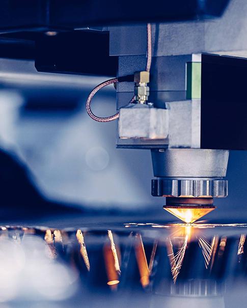
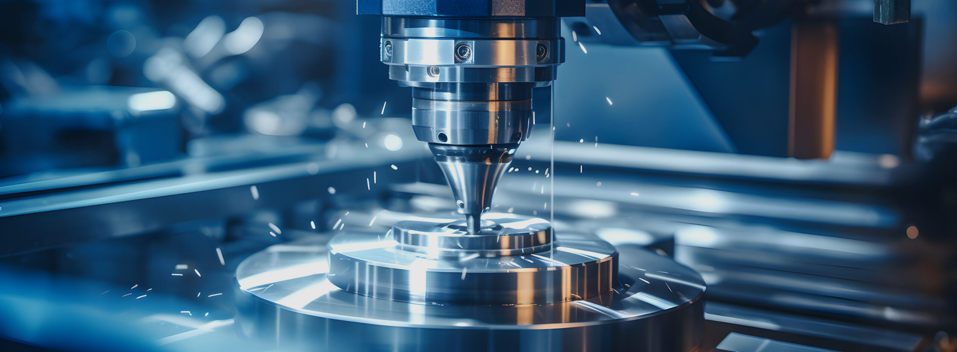
엔지니어의 머릿속에 있는 개념이 당신의 손에 있는 실제 부품으로 이어지는 여정은 현대 제조의 매혹적인 업적입니다. 이 과정의 핵심에는 중요한 전환이 있습니다. 바로 디지털 CAD 모델을 CNC 기계가 이해하고 실행할 수 있는 명령으로 변환하는 것입니다. 설계에서 현실로 이어지는 이러한 원활한 흐름이 현대 기계 부품의 정밀성과 복잡성을 가능하게 합니다. 이 기사에서는 CAD 파일을 완성된 CNC 가공 부품으로 변환하는 데 필요한 필수 단계, 소프트웨어 및 고려 사항을 설명합니다.디지털 스레드: CAD 설계부터 CAM 프로그래밍, CNC 가공을 통한 물리적 부품까지. 1단계: 기초 - CAD 모델 생성 모든 것은 컴퓨터 지원 설계(CAD)에서 시작됩니다. SolidWorks, Autodesk Fusion 360, AutoCAD, Siemens NX, Creo Parametric과 같은 소프트웨어를 사용하여 부품의 상세한 2D 또는 3D 모델을 만듭니다. · 정의: 원하는 부품의 모든 기하학적 데이터(치수, 허용 오차, 나사산, 특징)를 담은 디지털 청사진입니다.· 주요 출력: 최종 설계는 다양한 다른 소프트웨어에서 읽을 수 있는 중립 파일 형식으로 내보내집니다. 이러한 변환에 가장 일반적으로 사용되는 형식은 STEP(.step 또는 .stp) 또는 IGES(.iges)이며, 솔리드 지오메트리 정보를 보존합니다. 동일한 소프트웨어 생태계 내에서는 기본 형식 파일(예: SolidWorks의 경우 .SLDPRT)도 사용됩니다. 이 단계에서는 제조가능성 설계(DFM)가 매우 중요합니다. 설계자는 CNC 가공의 성능과 한계를 고려해야 합니다. · 도구 접근성: 절삭 도구가 모든 기능에 물리적으로 도달할 수 있는가?· 내부 날카로운 모서리: 대부분의 절삭 공구는 원통형이어서 완벽한 내부 날카로운 모서리를 만드는 것은 불가능합니다. 항상 반경이 필요합니다.· 벽 두께: 매우 얇은 벽은 진동이나 파손 없이 가공하기 어려울 수 있습니다.· 재료 선택: 재료(알루미늄, 강철, 플라스틱 등)의 선택은 가공 전략, 도구 선택 및 비용에 직접적인 영향을 미칩니다. 2단계: 브리지 - CAM 소프트웨어를 사용한 번역 CAD 모델은 '무엇', 즉 최종 형상을 정의합니다. 컴퓨터 지원 제조(CAM) 소프트웨어는 '어떻게', 즉 가공 프로세스를 정의합니다. · 설명: CAM 소프트웨어(종종 Fusion 360과 같은 CAD 소프트웨어의 모듈 또는 Mastercam과 같은 독립형 프로그램)가 CAD 모델을 가져옵니다. 프로그래머는 이 모델을 사용하여 공구 경로(공작물 위에서 공구의 이동을 지시하는 일련의 명령)를 생성합니다.· CAM의 주요 활동: 1. 설정 방향: 원자재(재고)를 기계 바이스나 고정 장치에 어떻게 고정할지, 어느 쪽을 먼저 가공할지 정의합니다. 2. 도구 선택: 디지털 라이브러리에서 적절한 절삭 도구(엔드밀, 드릴, 탭 등)를 선택하고 직경, 길이, 재료를 지정합니다. 3. 툴패스 정의: 다음과 같은 작업 시퀀스 생성: · 거친 작업: 많은 양의 재료를 빠르게 제거하는 작업입니다. · 마무리: 필요한 표면 마감과 엄격한 허용 오차를 달성하기 위해 마지막 단계를 만듭니다. · 드릴링: 구멍을 만드는 것. · 윤곽 가공: 부품의 외부 모양을 프로파일링합니다. 4. 매개변수 설정: 스핀들 속도(RPM), 이송 속도(공구가 움직이는 속도), 절삭 깊이와 같은 중요한 값을 입력합니다.CAM 소프트웨어는 절삭 공구가 부품을 만드는 데 필요한 정확한 경로를 보여주는 시각적 툴 경로를 생성합니다. 3단계: 기계 언어 - G-코드로의 후처리 CAM에서 생성된 툴패스는 아직 기계에 적용할 준비가 되지 않았습니다. 일반적인 툴패스이며, 포스트 프로세서가 번역기 역할을 합니다. · 정의: 포스트 프로세서는 일반적인 툴패스 데이터를 특정 G코드 파일로 변환하는 소프트웨어 플러그인(종종 CNC 기계의 브랜드와 모델에 따라 다름)입니다.· G 코드란 무엇인가요? G 코드는 CNC 기계의 모든 동작(이동, 속도, 이송, 냉각수 켜기/끄기, 공구 교환 등)을 제어하는 표준화된 프로그래밍 언어입니다(선형 이동에는 G01, 스핀들 시작에는 M03과 같은 명령 사용).· 필요성: CNC 컨트롤러(예: Fanuc, Haas, Heidenhain)마다 G 코드 방식이 약간씩 다릅니다. 포스트 프로세서는 출력 파일이 대상 기계에 완벽하게 맞춰지도록 하여 충돌이나 오류를 방지합니다. 이 단계의 최종 출력은 G 코드 프로그램을 포함하는 .NC 또는 .TXT 파일입니다. 4단계: 실행 - CNC 기계에서 프로그램 실행 G코드 프로그램이 준비되면 기계공이 작업을 시작합니다. 1. 설치: 원자재를 기계 베드에 단단히 고정합니다. 적합한 공구를 기계의 공구 교환기 또는 캐러셀에 장착합니다. 각 공구의 길이와 직경 오프셋을 기계 컨트롤러에서 정확하게 측정합니다.2. 작업 영점 설정: 기계공은 작업물에 대한 프로그램의 "영점"(원점)을 정의하여 기계에 해당 부품이 좌표계에서 어디에 있는지 알려줍니다.3. 검증: 실제 자료에 프로그램을 실행하기 전에 오류나 잠재적 충돌을 확인하기 위해 종종 연습 실행이나 시뮬레이션을 수행합니다.4. 가공: G 코드 프로그램이 기계 컨트롤러에 로드됩니다. 시작 버튼을 누르면 기계가 자동으로 명령을 실행하여 부품이 완성될 때까지 재료를 절단합니다. 결론: 간소화된 디지털 스레드 CAD에서 CNC로 이어지는 과정은 통합 디지털 제조의 강력한 사례입니다. CAD의 DFM(Design-of-Factory), CAM의 툴패스 생성, G코드 후처리, 그리고 정밀한 기계 가공에 이르기까지 모든 단계를 이해함으로써 엔지니어와 기계 기술자는 고품질 부품을 효율적이고 정확하게 생산하기 위해 협력할 수 있습니다. 이러한 디지털 스레드는 프로토타입 제작 및 생산 속도를 높일 뿐만 아니라, 수작업으로는 불가능했던 매우 복잡한 형상을 제작할 수 있는 잠재력을 열어줍니다. 면책 조항: 본 기사에 사용된 이미지는 예시 목적으로 사용되었으며, 실제 출판물에서는 원본 또는 라이선스를 받은 고해상도 이미지와 특정 소프트웨어 스크린샷이 사용됩니다.
 뉴스레터를 구독하세요